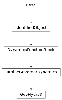
cimpy.cgmes_v2_4_15.GovHydro3 module
- class cimpy.cgmes_v2_4_15.GovHydro3.GovHydro3(at=0.0, db1=0.0, db2=0.0, dturb=0.0, eps=0.0, governorControl=False, gv1=0.0, gv2=0.0, gv3=0.0, gv4=0.0, gv5=0.0, gv6=0.0, h0=0.0, k1=0.0, k2=0.0, kg=0.0, ki=0.0, mwbase=0.0, pgv1=0.0, pgv2=0.0, pgv3=0.0, pgv4=0.0, pgv5=0.0, pgv6=0.0, pmax=0.0, pmin=0.0, qnl=0.0, relec=0.0, rgate=0.0, td=0.0, tf=0.0, tp=0.0, tt=0.0, tw=0.0, velcl=0.0, velop=0.0, *args, **kw_args)[source]
Modified IEEE Hydro Governor-Turbine Model. This model differs from that defined in the IEEE modeling guideline paper in that the limits on gate position and velocity do not permit “wind up” of the upstream signals.
- at:
Turbine gain (At). Typical Value = 1.2. Default: 0.0
- db1:
Intentional dead-band width (db1). Unit = Hz. Typical Value = 0. Default: 0.0
- db2:
Unintentional dead-band (db2). Unit = MW. Typical Value = 0. Default: 0.0
- dturb:
Turbine damping factor (Dturb). Typical Value = 0.2. Default: 0.0
- eps:
Intentional db hysteresis (eps). Unit = Hz. Typical Value = 0. Default: 0.0
- governorControl:
Governor control flag (Cflag). true = PID control is active false = double derivative control is active. Typical Value = true. Default: False
- gv1:
Nonlinear gain point 1, PU gv (Gv1). Typical Value = 0. Default: 0.0
- gv2:
Nonlinear gain point 2, PU gv (Gv2). Typical Value = 0. Default: 0.0
- gv3:
Nonlinear gain point 3, PU gv (Gv3). Typical Value = 0. Default: 0.0
- gv4:
Nonlinear gain point 4, PU gv (Gv4). Typical Value = 0. Default: 0.0
- gv5:
Nonlinear gain point 5, PU gv (Gv5). Typical Value = 0. Default: 0.0
- gv6:
Nonlinear gain point 6, PU gv (Gv6). Typical Value = 0. Default: 0.0
- h0:
Turbine nominal head (H0). Typical Value = 1. Default: 0.0
- k1:
Derivative gain (K1). Typical Value = 0.01. Default: 0.0
- k2:
Double derivative gain, if Cflag = -1 (K2). Typical Value = 2.5. Default: 0.0
- kg:
Gate servo gain (Kg). Typical Value = 2. Default: 0.0
- ki:
Integral gain (Ki). Typical Value = 0.5. Default: 0.0
- mwbase:
Base for power values (MWbase) (> 0). Unit = MW. Default: 0.0
- pgv1:
Nonlinear gain point 1, PU power (Pgv1). Typical Value = 0. Default: 0.0
- pgv2:
Nonlinear gain point 2, PU power (Pgv2). Typical Value = 0. Default: 0.0
- pgv3:
Nonlinear gain point 3, PU power (Pgv3). Typical Value = 0. Default: 0.0
- pgv4:
Nonlinear gain point 4, PU power (Pgv4). Typical Value = 0. Default: 0.0
- pgv5:
Nonlinear gain point 5, PU power (Pgv5). Typical Value = 0. Default: 0.0
- pgv6:
Nonlinear gain point 6, PU power (Pgv6). Typical Value = 0. Default: 0.0
- pmax:
Maximum gate opening, PU of MWbase (Pmax). Typical Value = 1. Default: 0.0
- pmin:
Minimum gate opening, PU of MWbase (Pmin). Typical Value = 0. Default: 0.0
- qnl:
No-load turbine flow at nominal head (Qnl). Typical Value = 0.08. Default: 0.0
- relec:
Steady-state droop, PU, for electrical power feedback (Relec). Typical Value = 0.05. Default: 0.0
- rgate:
Steady-state droop, PU, for governor output feedback (Rgate). Typical Value = 0. Default: 0.0
- td:
Input filter time constant (Td). Typical Value = 0.05. Default: 0.0
- tf:
Washout time constant (Tf). Typical Value = 0.1. Default: 0.0
- tp:
Gate servo time constant (Tp). Typical Value = 0.05. Default: 0.0
- tt:
Power feedback time constant (Tt). Typical Value = 0.2. Default: 0.0
- tw:
Water inertia time constant (Tw). Typical Value = 1. Default: 0.0
- velcl:
Maximum gate closing velocity (Velcl). Unit = PU/sec. Typical Value = -0.2. Default: 0.0
- velop:
Maximum gate opening velocity (Velop). Unit = PU/sec. Typical Value = 0.2. Default: 0.0
Documentation of parent class TurbineGovernorDynamics:
Turbine-governor function block whose behavior is described by reference to a standard model
- AsynchronousMachineDynamics:
Asynchronous machine model with which this turbine-governor model is associated. Default: None
- SynchronousMachineDynamics:
Turbine-governor model associated with this synchronous machine model. Default: “list”
- TurbineLoadControllerDynamics:
Turbine load controller providing input to this turbine-governor. Default: None
Documentation of parent class DynamicsFunctionBlock:
Abstract parent class for all Dynamics function blocks.
- enabled:
Function block used indicator. true = use of function block is enabled false = use of function block is disabled. Default: False
Documentation of parent class IdentifiedObject:
This is a root class to provide common identification for all classes needing identification and naming attributes.
- DiagramObjects:
The domain object to which this diagram object is associated. Default: “list”
- description:
The description is a free human readable text describing or naming the object. It may be non unique and may not correlate to a naming hierarchy. Default: ‘’
- energyIdentCodeEic:
The attribute is used for an exchange of the EIC code (Energy identification Code). The length of the string is 16 characters as defined by the EIC code. References: Default: ‘’
- mRID:
Master resource identifier issued by a model authority. The mRID is globally unique within an exchange context. Global uniqueness is easily achieved by using a UUID, as specified in RFC 4122, for the mRID. The use of UUID is strongly recommended. For CIMXML data files in RDF syntax conforming to IEC 61970-552 Edition 1, the mRID is mapped to rdf:ID or rdf:about attributes that identify CIM object elements. Default: ‘’
- name:
The name is any free human readable and possibly non unique text naming the object. Default: ‘’
- shortName:
The attribute is used for an exchange of a human readable short name with length of the string 12 characters maximum. Default: ‘’
Inheritance Diagram:
