cimpy.cgmes_v2_4_15.Terminal module
- class cimpy.cgmes_v2_4_15.Terminal.Terminal(ConverterDCSides='list', ConductingEquipment=None, phases=None, RegulatingControl=None, TieFlow='list', TransformerEnd='list', ConnectivityNode=None, HasFirstMutualCoupling='list', HasSecondMutualCoupling='list', SvPowerFlow=None, RemoteInputSignal='list', TopologicalNode=None, *args, **kw_args)[source]
An AC electrical connection point to a piece of conducting equipment. Terminals are connected at physical connection points called connectivity nodes.
- ConverterDCSides
Point of common coupling terminal for this converter DC side. It is typically the terminal on the power transformer (or switch) closest to the AC network. The power flow measurement must be the sum of all flows into the transformer. Default: “list”
- ConductingEquipment
The conducting equipment of the terminal. Conducting equipment have terminals that may be connected to other conducting equipment terminals via connectivity nodes or topological nodes. Default: None
- phases
Represents the normal network phasing condition. If the attribute is missing three phases (ABC or ABCN) shall be assumed. Default: None
- RegulatingControl
The terminal associated with this regulating control. The terminal is associated instead of a node, since the terminal could connect into either a topological node (bus in bus-branch model) or a connectivity node (detailed switch model). Sometimes it is useful to model regulation at a terminal of a bus bar object since the bus bar can be present in both a bus-branch model or a model with switch detail. Default: None
- TieFlow
The control area tie flows to which this terminal associates. Default: “list”
- TransformerEnd
All transformer ends connected at this terminal. Default: “list”
- ConnectivityNode
Terminals interconnected with zero impedance at a this connectivity node. Default: None
- HasFirstMutualCoupling
Mutual couplings associated with the branch as the first branch. Default: “list”
- HasSecondMutualCoupling
Mutual couplings with the branch associated as the first branch. Default: “list”
- SvPowerFlow
The power flow state variable associated with the terminal. Default: None
- RemoteInputSignal
Input signal coming from this terminal. Default: “list”
- TopologicalNode
The terminals associated with the topological node. This can be used as an alternative to the connectivity node path to terminal, thus making it unneccesary to model connectivity nodes in some cases. Note that if connectivity nodes are in the model, this association would probably not be used as an input specification. Default: None
Documentation of parent class ACDCTerminal:
An electrical connection point (AC or DC) to a piece of conducting equipment. Terminals are connected at physical connection points called connectivity nodes.
- BusNameMarker
The bus name marker used to name the bus (topological node). Default: None
- sequenceNumber
The orientation of the terminal connections for a multiple terminal conducting equipment. The sequence numbering starts with 1 and additional terminals should follow in increasing order. The first terminal is the starting point for a two terminal branch. Default: 0
- OperationalLimitSet
Default: “list”
- Measurements
Measurements associated with this terminal defining where the measurement is placed in the network topology. It may be used, for instance, to capture the sensor position, such as a voltage transformer (PT) at a busbar or a current transformer (CT) at the bar between a breaker and an isolator. Default: “list”
- connected
The connected status is related to a bus-branch model and the topological node to terminal relation. True implies the terminal is connected to the related topological node and false implies it is not. In a bus-branch model, the connected status is used to tell if equipment is disconnected without having to change the connectivity described by the topological node to terminal relation. A valid case is that conducting equipment can be connected in one end and open in the other. In particular for an AC line segment, where the reactive line charging can be significant, this is a relevant case. Default: False
Documentation of parent class IdentifiedObject:
This is a root class to provide common identification for all classes needing identification and naming attributes.
- DiagramObjects
The domain object to which this diagram object is associated. Default: “list”
- mRID
Master resource identifier issued by a model authority. The mRID is globally unique within an exchange context. Global uniqueness is easily achieved by using a UUID, as specified in RFC 4122, for the mRID. The use of UUID is strongly recommended. For CIMXML data files in RDF syntax conforming to IEC 61970-552 Edition 1, the mRID is mapped to rdf:ID or rdf:about attributes that identify CIM object elements. Default: ‘’
- name
The name is any free human readable and possibly non unique text naming the object. Default: ‘’
- description
The description is a free human readable text describing or naming the object. It may be non unique and may not correlate to a naming hierarchy. Default: ‘’
- energyIdentCodeEic
The attribute is used for an exchange of the EIC code (Energy identification Code). The length of the string is 16 characters as defined by the EIC code. References: Default: ‘’
- shortName
The attribute is used for an exchange of a human readable short name with length of the string 12 characters maximum. Default: ‘’
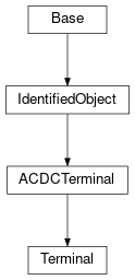
Inheritance Diagram: