cimpy.cgmes_v2_4_15.ExcAC2A module
- class cimpy.cgmes_v2_4_15.ExcAC2A.ExcAC2A(tb=0, tc=0, ka=0.0, ta=0, vamax=0.0, vamin=0.0, kb=0.0, kb1=0.0, vrmax=0.0, vrmin=0.0, te=0, vfemax=0.0, kh=0.0, kf=0.0, kl=0.0, vlr=0.0, kl1=0.0, ks=0.0, tf=0, kc=0.0, kd=0.0, ke=0.0, ve1=0.0, seve1=0.0, ve2=0.0, seve2=0.0, hvgate=False, lvgate=False, *args, **kw_args)[source]
Modified IEEE AC2A alternator-supplied rectifier excitation system with different field current limit.
- tb
Voltage regulator time constant (Tb). Typical Value = 0. Default: 0
- tc
Voltage regulator time constant (T). Typical Value = 0. Default: 0
- ka
Voltage regulator gain (Ka). Typical Value = 400. Default: 0.0
- ta
Voltage regulator time constant (Ta). Typical Value = 0.02. Default: 0
- vamax
Maximum voltage regulator output (V). Typical Value = 8. Default: 0.0
- vamin
Minimum voltage regulator output (V). Typical Value = -8. Default: 0.0
- kb
Second stage regulator gain (Kb) (>0). Exciter field current controller gain. Typical Value = 25. Default: 0.0
- kb1
Second stage regulator gain (Kb1). It is exciter field current controller gain used as alternative to Kb to represent a variant of the ExcAC2A model. Typical Value = 25. Default: 0.0
- vrmax
Maximum voltage regulator outputs (Vrmax). Typical Value = 105. Default: 0.0
- vrmin
Minimum voltage regulator outputs (Vrmin). Typical Value = -95. Default: 0.0
- te
Exciter time constant, integration rate associated with exciter control (Te). Typical Value = 0.6. Default: 0
- vfemax
Exciter field current limit reference (Vfemax). Typical Value = 4.4. Default: 0.0
- kh
Exciter field current feedback gain (Kh). Typical Value = 1. Default: 0.0
- kf
Excitation control system stabilizer gains (Kf). Typical Value = 0.03. Default: 0.0
- kl
Exciter field current limiter gain (Kl). Typical Value = 10. Default: 0.0
- vlr
Maximum exciter field current (Vlr). Typical Value = 4.4. Default: 0.0
- kl1
Coefficient to allow different usage of the model (Kl1). Typical Value = 1. Default: 0.0
- ks
Coefficient to allow different usage of the model-speed coefficient (Ks). Typical Value = 0. Default: 0.0
- tf
Excitation control system stabilizer time constant (Tf). Typical Value = 1. Default: 0
- kc
Rectifier loading factor proportional to commutating reactance (Kc). Typical Value = 0.28. Default: 0.0
- kd
Demagnetizing factor, a function of exciter alternator reactances (Kd). Typical Value = 0.35. Default: 0.0
- ke
Exciter constant related to self-excited field (Ke). Typical Value = 1. Default: 0.0
- ve1
Exciter alternator output voltages back of commutating reactance at which saturation is defined (Ve). Typical Value = 4.4. Default: 0.0
- seve1
Exciter saturation function value at the corresponding exciter voltage, Ve, back of commutating reactance (Se[Ve]). Typical Value = 0.037. Default: 0.0
- ve2
Exciter alternator output voltages back of commutating reactance at which saturation is defined (Ve). Typical Value = 3.3. Default: 0.0
- seve2
Exciter saturation function value at the corresponding exciter voltage, Ve, back of commutating reactance (Se[Ve]). Typical Value = 0.012. Default: 0.0
- hvgate
Indicates if HV gate is active (HVgate). true = gate is used false = gate is not used. Typical Value = true. Default: False
- lvgate
Indicates if LV gate is active (LVgate). true = gate is used false = gate is not used. Typical Value = true. Default: False
Documentation of parent class ExcitationSystemDynamics:
Excitation system function block whose behavior is described by reference to a standard model
- SynchronousMachineDynamics
Synchronous machine model with which this excitation system model is associated. Default: None
- PowerSystemStabilizerDynamics
Power system stabilizer model associated with this excitation system model. Default: None
- PFVArControllerType1Dynamics
Power Factor or VAr controller Type I model associated with this excitation system model. Default: None
- VoltageCompensatorDynamics
Voltage compensator model associated with this excitation system model. Default: None
- DiscontinuousExcitationControlDynamics
Discontinuous excitation control model associated with this excitation system model. Default: None
- UnderexcitationLimiterDynamics
Undrexcitation limiter model associated with this excitation system model. Default: None
- PFVArControllerType2Dynamics
Power Factor or VAr controller Type II model associated with this excitation system model. Default: None
- OverexcitationLimiterDynamics
Overexcitation limiter model associated with this excitation system model. Default: None
Documentation of parent class DynamicsFunctionBlock:
Abstract parent class for all Dynamics function blocks.
- enabled
Function block used indicator. true = use of function block is enabled false = use of function block is disabled. Default: False
Documentation of parent class IdentifiedObject:
This is a root class to provide common identification for all classes needing identification and naming attributes.
- DiagramObjects
The domain object to which this diagram object is associated. Default: “list”
- mRID
Master resource identifier issued by a model authority. The mRID is globally unique within an exchange context. Global uniqueness is easily achieved by using a UUID, as specified in RFC 4122, for the mRID. The use of UUID is strongly recommended. For CIMXML data files in RDF syntax conforming to IEC 61970-552 Edition 1, the mRID is mapped to rdf:ID or rdf:about attributes that identify CIM object elements. Default: ‘’
- name
The name is any free human readable and possibly non unique text naming the object. Default: ‘’
- description
The description is a free human readable text describing or naming the object. It may be non unique and may not correlate to a naming hierarchy. Default: ‘’
- energyIdentCodeEic
The attribute is used for an exchange of the EIC code (Energy identification Code). The length of the string is 16 characters as defined by the EIC code. References: Default: ‘’
- shortName
The attribute is used for an exchange of a human readable short name with length of the string 12 characters maximum. Default: ‘’
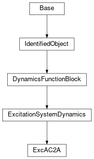
Inheritance Diagram: