cimpy.cgmes_v2_4_15.NonlinearShuntCompensator module
- class cimpy.cgmes_v2_4_15.NonlinearShuntCompensator.NonlinearShuntCompensator(NonlinearShuntCompensatorPoints='list', *args, **kw_args)[source]
A non linear shunt compensator has bank or section admittance values that differs.
- NonlinearShuntCompensatorPoints
All points of the non-linear shunt compensator. Default: “list”
Documentation of parent class ShuntCompensator:
A shunt capacitor or reactor or switchable bank of shunt capacitors or reactors. A section of a shunt compensator is an individual capacitor or reactor. A negative value for reactivePerSection indicates that the compensator is a reactor. ShuntCompensator is a single terminal device. Ground is implied.
- aVRDelay
Time delay required for the device to be connected or disconnected by automatic voltage regulation (AVR). Default: 0
- grounded
Used for Yn and Zn connections. True if the neutral is solidly grounded. Default: False
- maximumSections
The maximum number of sections that may be switched in. Default: 0
- nomU
The voltage at which the nominal reactive power may be calculated. This should normally be within 10% of the voltage at which the capacitor is connected to the network. Default: 0.0
- normalSections
The normal number of sections switched in. Default: 0
- switchOnCount
The switch on count since the capacitor count was last reset or initialized. Default: 0
- switchOnDate
The date and time when the capacitor bank was last switched on. Default: ‘’
- voltageSensitivity
Voltage sensitivity required for the device to regulate the bus voltage, in voltage/reactive power. Default: 0.0
- sections
Shunt compensator sections in use. Starting value for steady state solution. Non integer values are allowed to support continuous variables. The reasons for continuous value are to support study cases where no discrete shunt compensators has yet been designed, a solutions where a narrow voltage band force the sections to oscillate or accommodate for a continuous solution as input. Default: 0.0
- SvShuntCompensatorSections
The state for the number of shunt compensator sections in service. Default: None
Documentation of parent class RegulatingCondEq:
A type of conducting equipment that can regulate a quantity (i.e. voltage or flow) at a specific point in the network.
- RegulatingControl
The regulating control scheme in which this equipment participates. Default: None
- controlEnabled
Specifies the regulation status of the equipment. True is regulating, false is not regulating. Default: False
Documentation of parent class ConductingEquipment:
The parts of the AC power system that are designed to carry current or that are conductively connected through terminals.
- BaseVoltage
All conducting equipment with this base voltage. Use only when there is no voltage level container used and only one base voltage applies. For example, not used for transformers. Default: None
- Terminals
Conducting equipment have terminals that may be connected to other conducting equipment terminals via connectivity nodes or topological nodes. Default: “list”
- SvStatus
The status state variable associated with this conducting equipment. Default: None
Documentation of parent class Equipment:
The parts of a power system that are physical devices, electronic or mechanical.
- aggregate
The single instance of equipment represents multiple pieces of equipment that have been modeled together as an aggregate. Examples would be power transformers or synchronous machines operating in parallel modeled as a single aggregate power transformer or aggregate synchronous machine. This is not to be used to indicate equipment that is part of a group of interdependent equipment produced by a network production program. Default: False
- EquipmentContainer
Container of this equipment. Default: None
- OperationalLimitSet
The operational limit sets associated with this equipment. Default: “list”
Documentation of parent class PowerSystemResource:
A power system resource can be an item of equipment such as a switch, an equipment container containing many individual items of equipment such as a substation, or an organisational entity such as sub-control area. Power system resources can have measurements associated.
- Controls
Regulating device governed by this control output. Default: “list”
- Measurements
The power system resource that contains the measurement. Default: “list”
- Location
Location of this power system resource. Default: None
Documentation of parent class IdentifiedObject:
This is a root class to provide common identification for all classes needing identification and naming attributes.
- DiagramObjects
The domain object to which this diagram object is associated. Default: “list”
- mRID
Master resource identifier issued by a model authority. The mRID is globally unique within an exchange context. Global uniqueness is easily achieved by using a UUID, as specified in RFC 4122, for the mRID. The use of UUID is strongly recommended. For CIMXML data files in RDF syntax conforming to IEC 61970-552 Edition 1, the mRID is mapped to rdf:ID or rdf:about attributes that identify CIM object elements. Default: ‘’
- name
The name is any free human readable and possibly non unique text naming the object. Default: ‘’
- description
The description is a free human readable text describing or naming the object. It may be non unique and may not correlate to a naming hierarchy. Default: ‘’
- energyIdentCodeEic
The attribute is used for an exchange of the EIC code (Energy identification Code). The length of the string is 16 characters as defined by the EIC code. References: Default: ‘’
- shortName
The attribute is used for an exchange of a human readable short name with length of the string 12 characters maximum. Default: ‘’
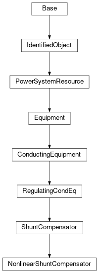
Inheritance Diagram: