cimpy.cgmes_v2_4_15.DCTerminal module
- class cimpy.cgmes_v2_4_15.DCTerminal.DCTerminal(DCConductingEquipment=None, *args, **kw_args)[source]
An electrical connection point to generic DC conducting equipment.
- DCConductingEquipment
Default: None
Documentation of parent class DCBaseTerminal:
An electrical connection point at a piece of DC conducting equipment. DC terminals are connected at one physical DC node that may have multiple DC terminals connected. A DC node is similar to an AC connectivity node. The model enforces that DC connections are distinct from AC connections.
- DCNode
Default: None
- DCTopologicalNode
See association end TopologicalNode.Terminal. Default: None
Documentation of parent class ACDCTerminal:
An electrical connection point (AC or DC) to a piece of conducting equipment. Terminals are connected at physical connection points called connectivity nodes.
- BusNameMarker
The bus name marker used to name the bus (topological node). Default: None
- sequenceNumber
The orientation of the terminal connections for a multiple terminal conducting equipment. The sequence numbering starts with 1 and additional terminals should follow in increasing order. The first terminal is the starting point for a two terminal branch. Default: 0
- OperationalLimitSet
Default: “list”
- Measurements
Measurements associated with this terminal defining where the measurement is placed in the network topology. It may be used, for instance, to capture the sensor position, such as a voltage transformer (PT) at a busbar or a current transformer (CT) at the bar between a breaker and an isolator. Default: “list”
- connected
The connected status is related to a bus-branch model and the topological node to terminal relation. True implies the terminal is connected to the related topological node and false implies it is not. In a bus-branch model, the connected status is used to tell if equipment is disconnected without having to change the connectivity described by the topological node to terminal relation. A valid case is that conducting equipment can be connected in one end and open in the other. In particular for an AC line segment, where the reactive line charging can be significant, this is a relevant case. Default: False
Documentation of parent class IdentifiedObject:
This is a root class to provide common identification for all classes needing identification and naming attributes.
- DiagramObjects
The domain object to which this diagram object is associated. Default: “list”
- mRID
Master resource identifier issued by a model authority. The mRID is globally unique within an exchange context. Global uniqueness is easily achieved by using a UUID, as specified in RFC 4122, for the mRID. The use of UUID is strongly recommended. For CIMXML data files in RDF syntax conforming to IEC 61970-552 Edition 1, the mRID is mapped to rdf:ID or rdf:about attributes that identify CIM object elements. Default: ‘’
- name
The name is any free human readable and possibly non unique text naming the object. Default: ‘’
- description
The description is a free human readable text describing or naming the object. It may be non unique and may not correlate to a naming hierarchy. Default: ‘’
- energyIdentCodeEic
The attribute is used for an exchange of the EIC code (Energy identification Code). The length of the string is 16 characters as defined by the EIC code. References: Default: ‘’
- shortName
The attribute is used for an exchange of a human readable short name with length of the string 12 characters maximum. Default: ‘’
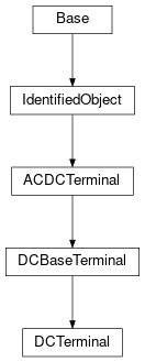
Inheritance Diagram: