cimpy.cgmes_v2_4_15.PowerTransformer module
- class cimpy.cgmes_v2_4_15.PowerTransformer.PowerTransformer(PowerTransformerEnd='list', beforeShCircuitHighestOperatingCurrent=0.0, beforeShCircuitHighestOperatingVoltage=0.0, beforeShortCircuitAnglePf=0.0, highSideMinOperatingU=0.0, isPartOfGeneratorUnit=False, operationalValuesConsidered=False, *args, **kw_args)[source]
An electrical device consisting of two or more coupled windings, with or without a magnetic core, for introducing mutual coupling between electric circuits. Transformers can be used to control voltage and phase shift (active power flow). A power transformer may be composed of separate transformer tanks that need not be identical. A power transformer can be modeled with or without tanks and is intended for use in both balanced and unbalanced representations. A power transformer typically has two terminals, but may have one (grounding), three or more terminals. The inherited association ConductingEquipment.BaseVoltage should not be used. The association from TransformerEnd to BaseVoltage should be used instead.
- PowerTransformerEnd
The power transformer of this power transformer end. Default: “list”
- beforeShCircuitHighestOperatingCurrent
The highest operating current (Ib in the IEC 60909-0) before short circuit (depends on network configuration and relevant reliability philosophy). It is used for calculation of the impedance correction factor KT defined in IEC 60909-0. Default: 0.0
- beforeShCircuitHighestOperatingVoltage
The highest operating voltage (Ub in the IEC 60909-0) before short circuit. It is used for calculation of the impedance correction factor KT defined in IEC 60909-0. This is worst case voltage on the low side winding (Section 3.7.1 in the standard). Used to define operating conditions. Default: 0.0
- beforeShortCircuitAnglePf
The angle of power factor before short circuit (phib in the IEC 60909-0). It is used for calculation of the impedance correction factor KT defined in IEC 60909-0. This is the worst case power factor. Used to define operating conditions. Default: 0.0
- highSideMinOperatingU
The minimum operating voltage (uQmin in the IEC 60909-0) at the high voltage side (Q side) of the unit transformer of the power station unit. A value well established from long-term operating experience of the system. It is used for calculation of the impedance correction factor KG defined in IEC 60909-0 Default: 0.0
- isPartOfGeneratorUnit
Indicates whether the machine is part of a power station unit. Used for short circuit data exchange according to IEC 60909 Default: False
- operationalValuesConsidered
It is used to define if the data (other attributes related to short circuit data exchange) defines long term operational conditions or not. Used for short circuit data exchange according to IEC 60909. Default: False
Documentation of parent class ConductingEquipment:
The parts of the AC power system that are designed to carry current or that are conductively connected through terminals.
- BaseVoltage
All conducting equipment with this base voltage. Use only when there is no voltage level container used and only one base voltage applies. For example, not used for transformers. Default: None
- Terminals
Conducting equipment have terminals that may be connected to other conducting equipment terminals via connectivity nodes or topological nodes. Default: “list”
- SvStatus
The status state variable associated with this conducting equipment. Default: None
Documentation of parent class Equipment:
The parts of a power system that are physical devices, electronic or mechanical.
- aggregate
The single instance of equipment represents multiple pieces of equipment that have been modeled together as an aggregate. Examples would be power transformers or synchronous machines operating in parallel modeled as a single aggregate power transformer or aggregate synchronous machine. This is not to be used to indicate equipment that is part of a group of interdependent equipment produced by a network production program. Default: False
- EquipmentContainer
Container of this equipment. Default: None
- OperationalLimitSet
The operational limit sets associated with this equipment. Default: “list”
Documentation of parent class PowerSystemResource:
A power system resource can be an item of equipment such as a switch, an equipment container containing many individual items of equipment such as a substation, or an organisational entity such as sub-control area. Power system resources can have measurements associated.
- Controls
Regulating device governed by this control output. Default: “list”
- Measurements
The power system resource that contains the measurement. Default: “list”
- Location
Location of this power system resource. Default: None
Documentation of parent class IdentifiedObject:
This is a root class to provide common identification for all classes needing identification and naming attributes.
- DiagramObjects
The domain object to which this diagram object is associated. Default: “list”
- mRID
Master resource identifier issued by a model authority. The mRID is globally unique within an exchange context. Global uniqueness is easily achieved by using a UUID, as specified in RFC 4122, for the mRID. The use of UUID is strongly recommended. For CIMXML data files in RDF syntax conforming to IEC 61970-552 Edition 1, the mRID is mapped to rdf:ID or rdf:about attributes that identify CIM object elements. Default: ‘’
- name
The name is any free human readable and possibly non unique text naming the object. Default: ‘’
- description
The description is a free human readable text describing or naming the object. It may be non unique and may not correlate to a naming hierarchy. Default: ‘’
- energyIdentCodeEic
The attribute is used for an exchange of the EIC code (Energy identification Code). The length of the string is 16 characters as defined by the EIC code. References: Default: ‘’
- shortName
The attribute is used for an exchange of a human readable short name with length of the string 12 characters maximum. Default: ‘’
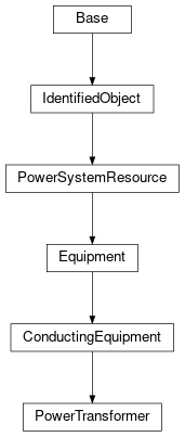
Inheritance Diagram: