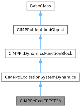
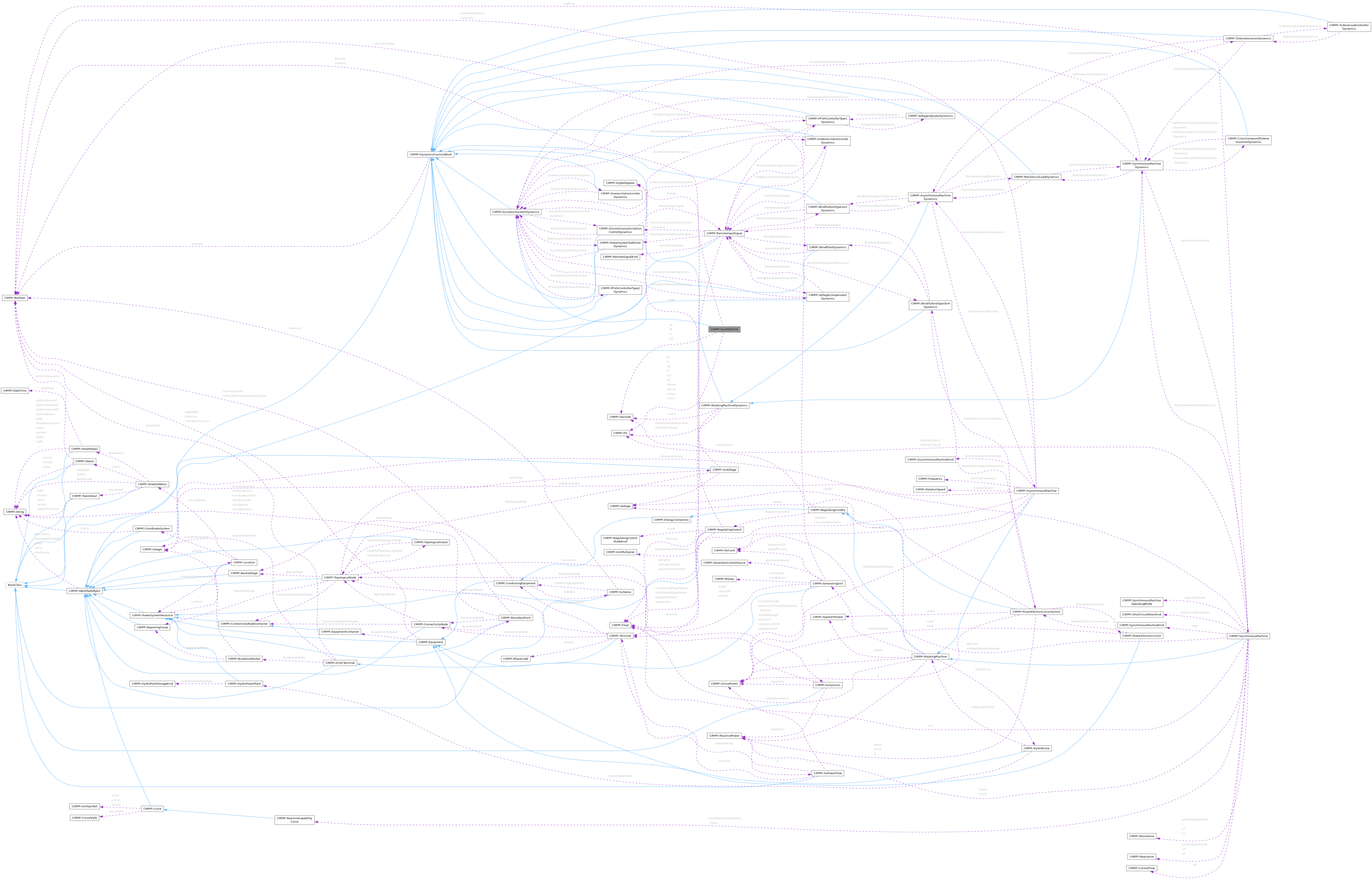
IEEE 421.5-2005 type ST3A model. Some static systems utilize a field voltage control loop to linearize the exciter control characteristic. This also makes the output independent of supply source variations until supply limitations are reached. These systems utilize a variety of controlled-rectifier designs: full thyristor complements or hybrid bridges in either series or shunt configurations. The power source can consist of only a potential source, either fed from the machine terminals or from internal windings. Some designs can have compound power sources utilizing both machine potential and current. These power sources are represented as phasor combinations of machine terminal current and voltage and are accommodated by suitable parameters in model type ST3A which is represented by ExcIEEEST3A. Reference: IEEE 421.5-2005, 7.3.
More...
|
|
static void | addConstructToMap (std::unordered_map< std::string, BaseClass *(*)()> &factory_map) |
|
static void | addPrimitiveAssignFnsToMap (std::unordered_map< std::string, assign_function > &assign_map) |
|
static void | addClassAssignFnsToMap (std::unordered_map< std::string, class_assign_function > &assign_map) |
|
static const BaseClassDefiner | declare () |
|
static void | addConstructToMap (std::unordered_map< std::string, BaseClass *(*)()> &factory_map) |
|
static void | addPrimitiveAssignFnsToMap (std::unordered_map< std::string, assign_function > &assign_map) |
|
static void | addClassAssignFnsToMap (std::unordered_map< std::string, class_assign_function > &assign_map) |
|
static const BaseClassDefiner | declare () |
|
static void | addConstructToMap (std::unordered_map< std::string, BaseClass *(*)()> &factory_map) |
|
static void | addPrimitiveAssignFnsToMap (std::unordered_map< std::string, assign_function > &assign_map) |
|
static void | addClassAssignFnsToMap (std::unordered_map< std::string, class_assign_function > &assign_map) |
|
static const BaseClassDefiner | declare () |
|
static void | addConstructToMap (std::unordered_map< std::string, BaseClass *(*)()> &factory_map) |
|
static void | addPrimitiveAssignFnsToMap (std::unordered_map< std::string, assign_function > &assign_map) |
|
static void | addClassAssignFnsToMap (std::unordered_map< std::string, class_assign_function > &assign_map) |
|
static const BaseClassDefiner | declare () |
|
static void | addConstructToMap (std::unordered_map< std::string, BaseClass *(*)()> &factory_map) |
|
static void | addPrimitiveAssignFnsToMap (std::unordered_map< std::string, assign_function > &assign_map) |
|
static void | addClassAssignFnsToMap (std::unordered_map< std::string, class_assign_function > &assign_map) |
|
static const CIMPP::BaseClassDefiner | declare () |
|
|
CIMPP::PU | ka |
| | Voltage regulator gain (KA) (> 0). This is parameter K in the IEEE standard. Typical value = 200. Default: 0.0.
|
|
CIMPP::PU | kc |
| | Rectifier loading factor proportional to commutating reactance (KC) (>= 0). Typical value = 0,2. Default: 0.0.
|
|
CIMPP::PU | kg |
| | Feedback gain constant of the inner loop field regulator (KG) (>= 0). Typical value = 1. Default: 0.0.
|
|
CIMPP::PU | ki |
| | Potential circuit gain coefficient (KI) (>= 0). Typical value = 0. Default: 0.0.
|
|
CIMPP::PU | km |
| | Forward gain constant of the inner loop field regulator (KM) (> 0). Typical value = 7,93. Default: 0.0.
|
|
CIMPP::PU | kp |
| | Potential circuit gain coefficient (KP) (> 0). Typical value = 6,15. Default: 0.0.
|
|
CIMPP::Seconds | ta |
| | Voltage regulator time constant (TA) (>= 0). Typical value = 0. Default: 0.0.
|
|
CIMPP::Seconds | tb |
| | Voltage regulator time constant (TB) (>= 0). Typical value = 10. Default: 0.0.
|
|
CIMPP::Seconds | tc |
| | Voltage regulator time constant (TC) (>= 0). Typical value = 1. Default: 0.0.
|
|
CIMPP::AngleDegrees | thetap |
| | Potential circuit phase angle (thetap). Typical value = 0. Default: 0.0.
|
|
CIMPP::Seconds | tm |
| | Forward time constant of inner loop field regulator (TM) (> 0). Typical value = 0,4. Default: 0.0.
|
|
CIMPP::PU | vbmax |
| | Maximum excitation voltage (VBMax) (> 0). Typical value = 6,9. Default: 0.0.
|
|
CIMPP::PU | vgmax |
| | Maximum inner loop feedback voltage (VGMax) (>= 0). Typical value = 5,8. Default: 0.0.
|
|
CIMPP::PU | vimax |
| | Maximum voltage regulator input limit (VIMAX) (> 0). Typical value = 0,2. Default: 0.0.
|
|
CIMPP::PU | vimin |
| | Minimum voltage regulator input limit (VIMIN) (< 0). Typical value = -0,2. Default: 0.0.
|
|
CIMPP::PU | vmmax |
| | Maximum inner loop output (VMMax) (> 0). Typical value = 1. Default: 0.0.
|
|
CIMPP::PU | vmmin |
| | Minimum inner loop output (VMMin) (<= 0). Typical value = 0. Default: 0.0.
|
|
CIMPP::PU | vrmax |
| | Maximum voltage regulator output (VRMAX) (> 0). Typical value = 10. Default: 0.0.
|
|
CIMPP::PU | vrmin |
| | Minimum voltage regulator output (VRMIN) (< 0). Typical value = -10. Default: 0.0.
|
|
CIMPP::PU | xl |
| | Reactance associated with potential source (XL) (>= 0). Typical value = 0,081. Default: 0.0.
|
|
CIMPP::DiscontinuousExcitationControlDynamics * | DiscontinuousExcitationControlDynamics |
| | Discontinuous excitation control model associated with this excitation system model. Default: nullptr.
|
|
CIMPP::OverexcitationLimiterDynamics * | OverexcitationLimiterDynamics |
| | Overexcitation limiter model associated with this excitation system model. Default: nullptr.
|
|
CIMPP::PFVArControllerType1Dynamics * | PFVArControllerType1Dynamics |
| | Power factor or VAr controller type 1 model associated with this excitation system model. Default: nullptr.
|
|
CIMPP::PFVArControllerType2Dynamics * | PFVArControllerType2Dynamics |
| | Power factor or VAr controller type 2 model associated with this excitation system model. Default: nullptr.
|
|
CIMPP::PowerSystemStabilizerDynamics * | PowerSystemStabilizerDynamics |
| | Power system stabilizer model associated with this excitation system model. Default: nullptr.
|
|
CIMPP::SynchronousMachineDynamics * | SynchronousMachineDynamics |
| | Synchronous machine model with which this excitation system model is associated. Default: nullptr.
|
|
CIMPP::UnderexcitationLimiterDynamics * | UnderexcitationLimiterDynamics |
| | Undrexcitation limiter model associated with this excitation system model. Default: nullptr.
|
|
CIMPP::VoltageCompensatorDynamics * | VoltageCompensatorDynamics |
| | Voltage compensator model associated with this excitation system model. Default: nullptr.
|
|
CIMPP::Boolean | enabled |
| | Function block used indicator. true = use of function block is enabled false = use of function block is disabled. Default: false.
|
|
std::list< CIMPP::DiagramObject * > | DiagramObjects |
| | The diagram objects that are associated with the domain object. Default: {}.
|
|
CIMPP::String | description |
| | The description is a free human readable text describing or naming the object. It may be non unique and may not correlate to a naming hierarchy. Default: "".
|
|
CIMPP::String | energyIdentCodeEic |
| | The attribute is used for an exchange of the EIC code (Energy identification Code). The length of the string is 16 characters as defined by the EIC code. For details on EIC scheme please refer to ENTSO-E web site. Default: "".
|
|
CIMPP::String | mRID |
| | Master resource identifier issued by a model authority. The mRID is unique within an exchange context. Global uniqueness is easily achieved by using a UUID, as specified in RFC 4122, for the mRID. The use of UUID is strongly recommended. For CIMXML data files in RDF syntax conforming to IEC 61970-552, the mRID is mapped to rdf:ID or rdf:about attributes that identify CIM object elements. Default: "".
|
|
CIMPP::String | name |
| | The name is any free human readable and possibly non unique text naming the object. Default: "".
|
|
CIMPP::String | shortName |
| | The attribute is used for an exchange of a human readable short name with length of the string 12 characters maximum. Default: "".
|
IEEE 421.5-2005 type ST3A model. Some static systems utilize a field voltage control loop to linearize the exciter control characteristic. This also makes the output independent of supply source variations until supply limitations are reached. These systems utilize a variety of controlled-rectifier designs: full thyristor complements or hybrid bridges in either series or shunt configurations. The power source can consist of only a potential source, either fed from the machine terminals or from internal windings. Some designs can have compound power sources utilizing both machine potential and current. These power sources are represented as phasor combinations of machine terminal current and voltage and are accommodated by suitable parameters in model type ST3A which is represented by ExcIEEEST3A. Reference: IEEE 421.5-2005, 7.3.

 1.15.0